In the past couple of months, had to go through a change in residence.
During the shifting, despite taking all care I could, the pit sustained minor damages. Fixed most of them.
Last week, my UFCP monitor (8") just died on me. Despite my best efforts, and getting hold of some really skillful technicians, I wasn't able to get it fixed.
Ordered myself a new 8" TFT monitor now.
Will have to rebuild my UFCP after the new monitor arrives.
29 July 2014
19 May 2014
18 May 2014
Fidgety Phidgets
This is a bit
technical post, and I make this post, only to record it for benefit of a future
pit builder using the same techniques as I.
While all the ‘Inputs’
in the bit are being handled by either Leo Bodnar’s cards, or by Teensey ++2.00
micro-controller boards. For my purposes, these means have proved to be quite
adequate.
While Arduino boards
could also be used for ‘Output’ purposes, but, long time ago, I chose to go
with Phidget boards.
Alan Dyre had
developed a nifty tool called “FS2Phidgets”, which cleanly interfaces the
Phidget boards with FSX/FSUIPC. It took some learning, but after that this
board/tool is a breeze to use.
Glenn “Tripod” Weston,
has provided a masterpiece of an interface tool called as ‘SuperScript’. This
LUA script interfaces the VRS SuperBug with FSUIPC and provides total control
over all data communication with the airplane.
The SuperScript
provides ‘Memory Offsets’ used by FSUIPC, which could be read/written to, to
interface the state of all cockpit annunciators, with any other driver board.
While programming the “FS
Variable” file for the FS2Phidgets, I came across two idiosyncrasies of the
script, which I thought need to be mentioned.
The SuperScript defines
memory offsets (in HEX) as, for example, “0x66CA”. However, if the same format
is used to declare the offset in FSVariable, it leads to unpredictable results.
I found that if the preceeding “0x” was deleted, (use only 66CA, from above
example), then the offsets worked flawlessly.
The second issue I
faced was in declaring the length of the memory offset. All the output scripts
provided by Tripod are one Byte (8 bits) long, except three which are two byte’s
long (Caution Panel and Left/Right Annunciator Panels). This was done, to
accommodate more than 8 bit assignments in these panel groups.
While declaring
FSVariables in FS2P, if I declared the length of offset as ‘Two’ bytes, then
the results were very unpredictable. It took me all of full day, to finally
figure my way out of this. I realized that FS2P is not able to correctly convert
the HEX to decimal, when using two byte long FS Variables.
Out of the three 2
byte groups that Tripod has provided, the Left/Right Annunciator Panel groups,
actually use only 8 bits, while the rest of the bits are kept for future use.
However, the Caution Panel group uses 10 bits of address space. I split these
two bytes into two single bytes offsets, and accordingly changed bit addresses of the
included parameters.
To illustrate, the
Caution Panel reads the Offset 0x66C0, and, it’s a 16 bit Unsigned Word. The offset
is two bytes long and declares variables from Bit0 till Bit9 (10 bits), while
the remaining six bits are kept free for future use.
I declared the FS2P
FSVariables in Offset 66C0 from Bit0 till Bit7 (8 bits) and then declared the
next memory offset (i.e. 66C1) and declared the Bit8 & Bit9 of the original
offset and Bit0 & Bit1 of the new offset, and voila, everything fit into
place.
I know this is boring,
but, am sure, will help someone someday.
BUNO 22358 is undergoing Taxi Trials
No pictures in today’s
update.
It’s been almost seven
months since, I started the physical fabrication part of the cockpit build. And
it’s four times that time, since I had been researching this subject.
I’m happy to finally
say, that Mk-1, Ver 1.00 of my “VRS Rhino Pit, BUNO 22358, AviaScorp Musings”
is finally up for complete systems integration checks.
The systems
integration checks were planned for the last weekend, but that got consumed
totally in fabricating the HUD gauge. Throughout the week, I was promising
myself, that this weekend, I WILL fire up the pit, and do atleast one test
flight.
I’m happy, that I did.
The pit is not
perfect. Not there, where I want it to be. It’s therefore, I call it a Mk-1, Ver
1.00.
Mk-1 build, when
complete, will have everything I had originally planned. Subsequent Marks, will
incorporate items that I had never planned originally for my pit, for example,
a fully collimated, externally projected HUD, Three overhead projectors instead
of three 23” monitors for the external displays, spanning various components of
the pit on multiple computers instead of a single computer it’s working off,
right now, and maybe, just maybe, if technologies like Occulus Rift mature, I
might consider moving along the VR road also. It’s also planned to make modules
of the pit, quickly replacable, so that I could modify the pit for different
airplanes that I love to fly.
Ver 1.00 of the pit is
just to ‘stop’ further fabrication, at whatever stage I presently am. I realized,
that as I fabricated different parts, my skills also improved. For example, the
HUD that I fabricated last week, was of a much better quality and design,
compared to (let’s say) a UFCP that was fabricated a few months ago, or the pit
tub that was designed and fabricated almost half a year ago. For the past few
months, all I was doing was, breaking the older parts and remaking newer
versions of them. Due to this, while the work continued on a feverish pace, the
pit was never nearing completion.
Future versions of
Mk-1 Pit, will replace the existing components with better built/finished
components. For example, I have realized that some of the annunciator lights
are too dim, or the LEDs are not installed correctly in their enclosures. Or, I’m
also considering fabricating/replacing the SPST/DPST mechanical switches with
electrically or magnetically held/latches switches to more accurately mimic the
actual airplane.
But, all that is for
the future and the coming weeks.
As I type this update,
a small video I have prepared of the state of the pit till today, and as I was
testing it earlier today, is getting uploaded.
That will explain the
current status of the pit much better than all the words out here.
placards and other
switches).
05 May 2014
HUD
During the initial planning stage itself, I had decided that my pit will not have an external HUD, and that I will use the HUD display provided by the VRS model itself.
The only reason for this initial decision, taken more than two years back, was; 'I didn't think it possible for me to be able to build myself a home-built, working, fully collimated HUD'.
A lot has changed in these two years. Thanks to the experiments by folks like Baldrick (on Hornetpit forums), and my own experiments, I now know, I could have built one.
And, I eventually will.
But, in the present design of my cockpit, there is just no more real estate left, to include a working HUD.
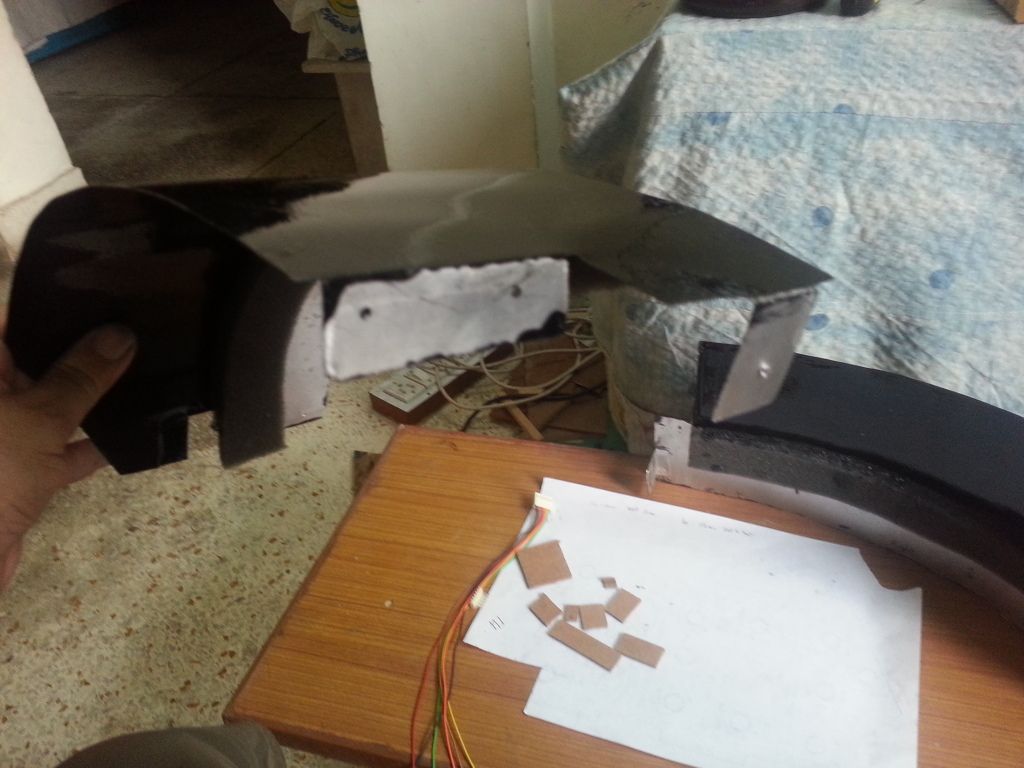
It's just about midnight on a Sunday. As per my original plans, I was supposed to complete my pit today. As of Friday, the only thing left for me to do was, design and build an AoA gauge and complete the wiring for all the annunciators.
As I sat down to design the AoA gauge, I decided to build a mock up HUD bracket also. Two day's of weekend, were completely consumed by building this simple device.

Having finished the fabrication part, I have started to layout the wiring harnesses also. Finished it for the 'Caution Panel' and the 'Master Arm Panel'. Tested it out, and it worked like a charm.
Was very happy to see the whole cockpit come alive with all the lights.
Unfortunately, I was too beat to take any pictures.
Will post them, as I complete more of wiring during the week.
The only reason for this initial decision, taken more than two years back, was; 'I didn't think it possible for me to be able to build myself a home-built, working, fully collimated HUD'.
A lot has changed in these two years. Thanks to the experiments by folks like Baldrick (on Hornetpit forums), and my own experiments, I now know, I could have built one.
And, I eventually will.
But, in the present design of my cockpit, there is just no more real estate left, to include a working HUD.
It's just about midnight on a Sunday. As per my original plans, I was supposed to complete my pit today. As of Friday, the only thing left for me to do was, design and build an AoA gauge and complete the wiring for all the annunciators.
As I sat down to design the AoA gauge, I decided to build a mock up HUD bracket also. Two day's of weekend, were completely consumed by building this simple device.
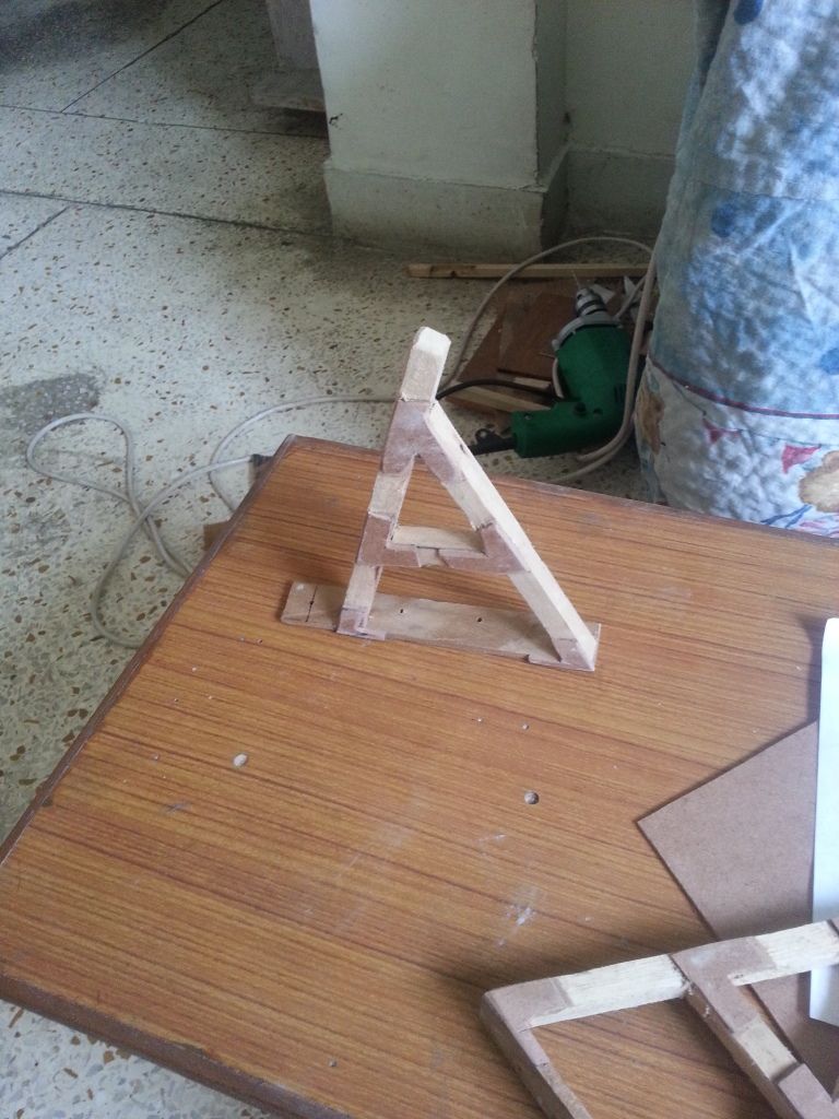 |
| Start of an 'abridged' HUD bracket. Pasted MDF cutouts at each joint for two reasons, it adds to the strength of the joint, and it also adds to the texture of the piece. This will look totally different, when it is filed, primed and painted. |
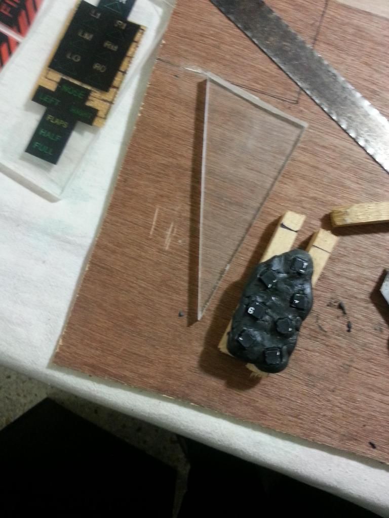
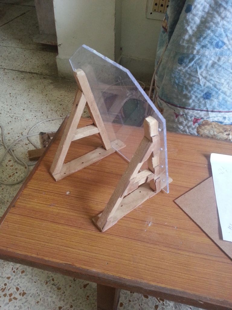 |
| Sizing it all up, with the combiner glass included |
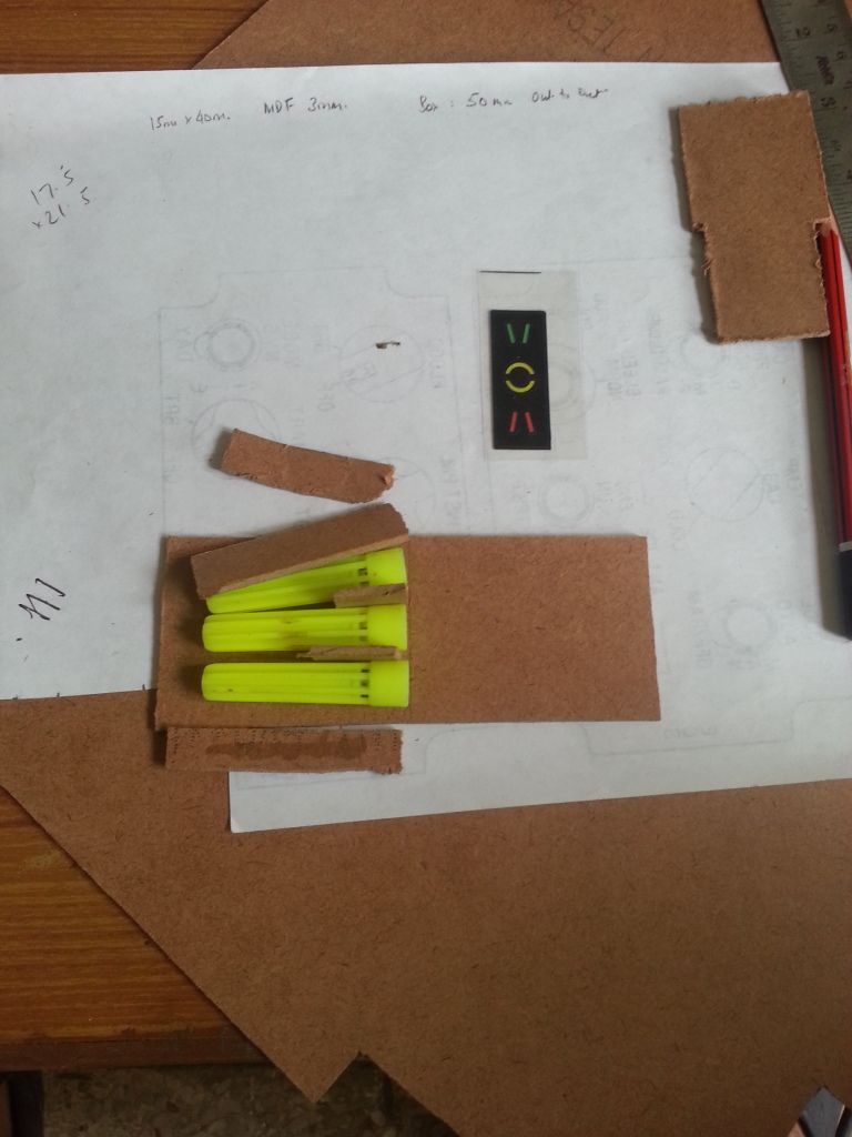 |
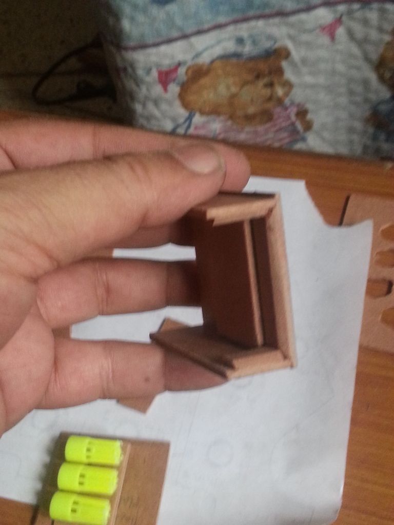
| Starting the build of AoA Gauge Sizing it all up. Taking measurements, planning the build. I decided to use the caps of disused sketch-pens of my daughter to make the LED mounts. These caps will ensure that the light of the respective LED stays confined and doesn't filter out to the other LED. Still need to figure out a way to block the very small holes near the base of the pen cap (seen towards the centre of the picture, facing right) |
 |
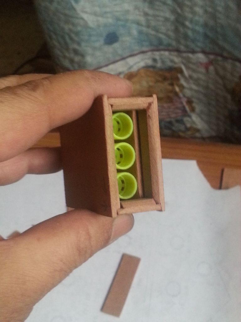
| Finalized my decision to go ahead with the use of pen caps. Cut them to the right size, and commenced the build. |
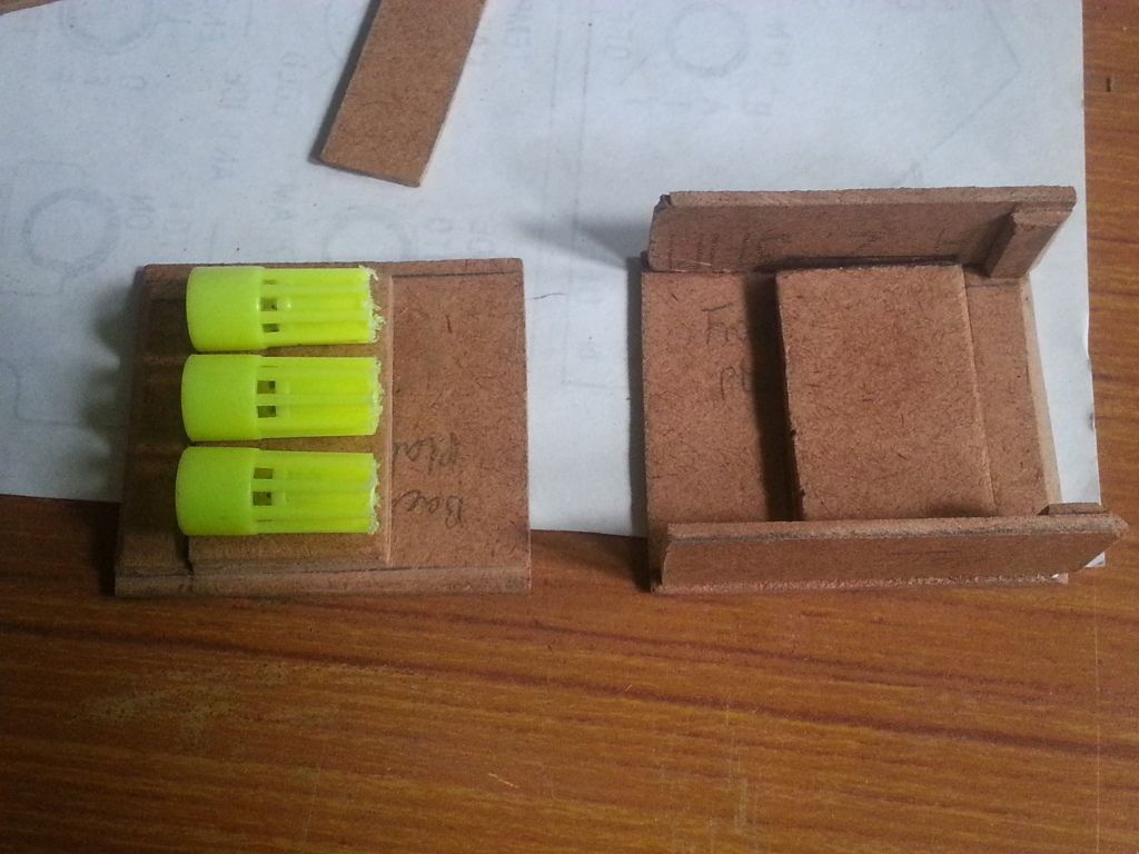 |
| The 'front' and the 'back' plate is now ready. I designed a correctly sized "groove" to accommodate a printout of AoA gauge markings on a transparency sheet. The measurements and eventual build is such that the front facia will correctly fit. |
 |
| Filing the finished the work piece |
 |
| Testing out the final fit, before I close it all up, and start to paint. I forgot to take a picture, but, I used the normal 'play dough' to seal the joints all around the pen caps. This positively ensures that no unnecessary light leaks out of the respective 'tube' |
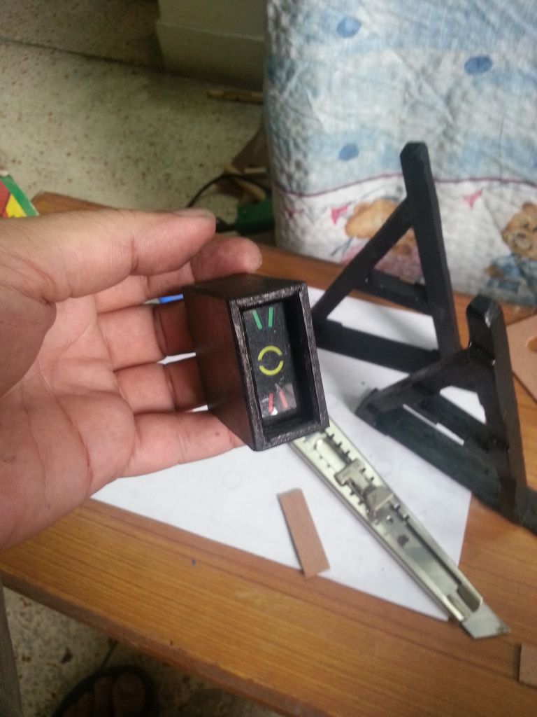 |
| Painted and all ready to be assembled. I felt very satisfied with the overall finish. It took really long to design and build this simple contraption. But, I'm glad I took the time. |
 |
| Assembled and all ready to be mounted in the pit The wiring will come next The bottle of play-dough, I mentioned previously, is visible in this picture. |
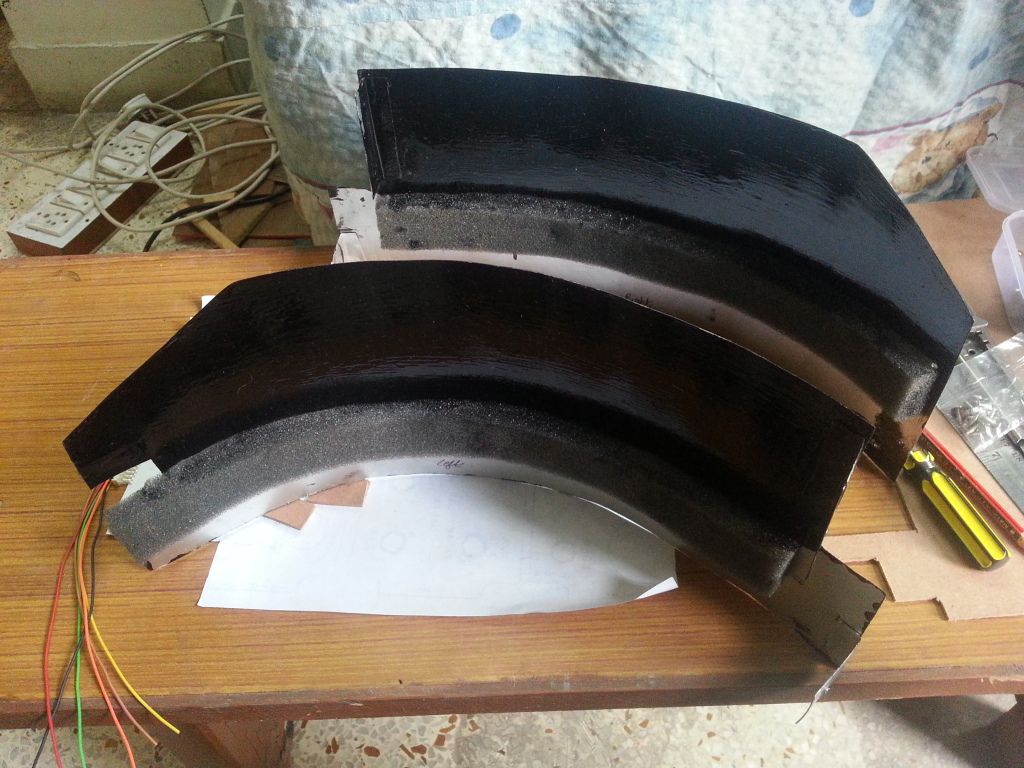 |
| Since the weekend was practically lost, just finishing up a simple piece, I decided to complete another remaining item. The left and right coaming panels. These will come on top of the Main Instrument Panel. Mark 'Wood' Killen, based on whose original design, the initial design of my pit was based, had done his coaming panels with plywood. Originally, that's how I had decided also. But, then, I decided to use sheet metal instead. I'm glad I did. Aluminium sheet metal is much easier to work with, compared to plywood, it also provides a better paint finish. Removal and installation of these panels is a bit intricate though. There is just no space to work in the pit anymore. |
 |
| I was trying to show the curved upper surface the paint finish in this picture, but the picture didn't come out as intended. |
Was very happy to see the whole cockpit come alive with all the lights.
Unfortunately, I was too beat to take any pictures.
Will post them, as I complete more of wiring during the week.
29 April 2014
Why do you build a cockpit
A question by an amused bystander, "Why would you build a home cockpit".
Answer by Baldrick, "Because, I can".
Baldrick, is another Rhino pit builder on 'Hornet Pit Builders' Forums, and is half way through an exemplary home pit build. I find the aforementioned quote by Baldrick, very simple, plain-speak, unassuming and truthful.
Over a period of last one year, I have been asked this very question by many friends and family, most of who (I'm sure) thought I had crossed over to the other side (of sanity). :)
Anyways, after a hectic weekend of trying to complete my pit, I wanted to complete the minor tidbits still left over in annunciator wiring. As luck would have it, I got delayed at work. Not to waste what little time I had today, I thought, I might as well calibrate my touch screen UFCP and other in-cockit displays.
Was quite content with how it panned out, eventually.
My digital camera is mostly in my daughter's custody, and I can never get my hands to it, when I need it in a hurry. So, most of my pictures get taken on my phone. The picture I took today, in less than ideal light, was not much to look at. So dabbed a bit with photobucket photo editing tools also. Just for fun.
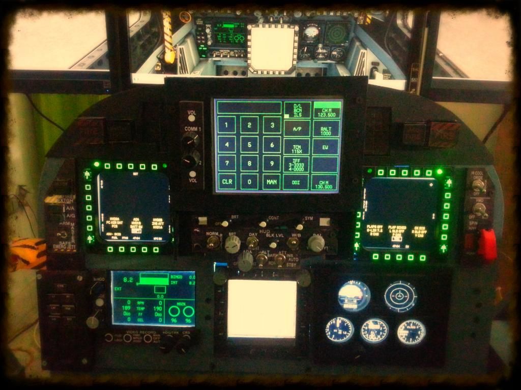
The real Rhino pit has spring loaded, two-position, clickable switches for HDG/CRS selectors. I had always thought that a rotary knob (a.k.a Altimeter Increment/Decrement Knob) to be a more ergonomic alternative. Don't mean to be rude to the folks at Boeing, but, I chose to make this modification in my pit. I embedded two 8 bit rotary encoders to drive the Heading and Course selector knobs on the EFD.
Did a 4 point calibration and 25 point linearization on the touch screen of the UFCP (will post a video of the same sometime later), and now it works like a charm.
Spent an enjoyable half hour positioning all the 2D gauges.
Am using the 'Panel Position' tool available on Avsim to position the undocked 2D panels across multiple monitors. It's an awesome tool. Instead of using the GUI method (physically dragging the panels across), I found that it's best to get into the config file and manually edit the values to derive a precise control over position of each panel. One can control the starting coordinates and height/width of each panel upto a pixel. Awesome!!!
Answer by Baldrick, "Because, I can".
Baldrick, is another Rhino pit builder on 'Hornet Pit Builders' Forums, and is half way through an exemplary home pit build. I find the aforementioned quote by Baldrick, very simple, plain-speak, unassuming and truthful.
Over a period of last one year, I have been asked this very question by many friends and family, most of who (I'm sure) thought I had crossed over to the other side (of sanity). :)
Anyways, after a hectic weekend of trying to complete my pit, I wanted to complete the minor tidbits still left over in annunciator wiring. As luck would have it, I got delayed at work. Not to waste what little time I had today, I thought, I might as well calibrate my touch screen UFCP and other in-cockit displays.
Was quite content with how it panned out, eventually.
My digital camera is mostly in my daughter's custody, and I can never get my hands to it, when I need it in a hurry. So, most of my pictures get taken on my phone. The picture I took today, in less than ideal light, was not much to look at. So dabbed a bit with photobucket photo editing tools also. Just for fun.
The real Rhino pit has spring loaded, two-position, clickable switches for HDG/CRS selectors. I had always thought that a rotary knob (a.k.a Altimeter Increment/Decrement Knob) to be a more ergonomic alternative. Don't mean to be rude to the folks at Boeing, but, I chose to make this modification in my pit. I embedded two 8 bit rotary encoders to drive the Heading and Course selector knobs on the EFD.
Did a 4 point calibration and 25 point linearization on the touch screen of the UFCP (will post a video of the same sometime later), and now it works like a charm.
Spent an enjoyable half hour positioning all the 2D gauges.
Am using the 'Panel Position' tool available on Avsim to position the undocked 2D panels across multiple monitors. It's an awesome tool. Instead of using the GUI method (physically dragging the panels across), I found that it's best to get into the config file and manually edit the values to derive a precise control over position of each panel. One can control the starting coordinates and height/width of each panel upto a pixel. Awesome!!!
28 April 2014
The cabling harnesses
I had planned to complete the cabling looms for all the in-cockpit indicators today.
As far as cockpit wiring goes, I have tried to keep it as 'modular' as possible. My job necessitates frequent house changes, and it was an original design criteria to make my pit portable. I have designed and fabricated it so, (that) I can take it apart in a day. Putting it all together again, will take a little longer though.
Each of the sub-panels (Left/Right Lower Console, Left/Right Upper Console have their own micro-controllers/HID controllers and the Main Instrument Panel has two HID controllers (Leo Bodnar BBI-32 and BU083X boards).
All the 'control' wiring for each sub-panel is self-contained. Each panel connects to the main cockpit through three connections, one for power another for USB, and one for all indicator/annunciator lights.
The layout of the wiring for each panel, has gone through a series of iterations. Each time, I had to completely take apart my old wiring, and redo it all over again. But, I think, I have now gotten it right. Just about.
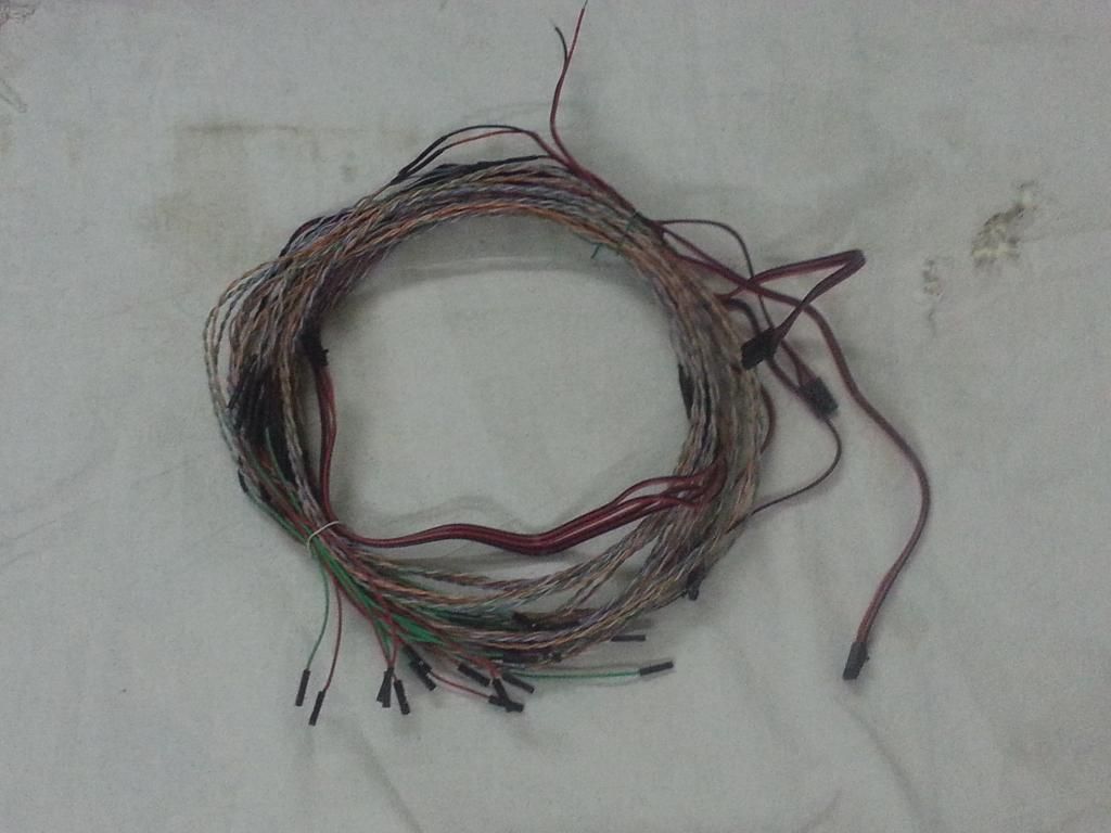
A few pictures of the annunciators cable harnesses are posted below. It was a LOT of work.
The Phidget controller board supports 64 outputs, and I have used each one of those. That is a total of 128 pins to wire up. Of all the wiring tasks for this pit, this one took the cake, by a lot of margin.
I'm glad, it's finally done.
Still need to make individual cable for the APU lamp, Gear Flasher and the Hook lamp. But, these are going to be individual cables with quick dismount fittings to interface. Plan to finish them tomorrow, after work.
Will start mounting the cable harnesses during the week, and hope to finish it in the next weekend.
As far as cockpit wiring goes, I have tried to keep it as 'modular' as possible. My job necessitates frequent house changes, and it was an original design criteria to make my pit portable. I have designed and fabricated it so, (that) I can take it apart in a day. Putting it all together again, will take a little longer though.
Each of the sub-panels (Left/Right Lower Console, Left/Right Upper Console have their own micro-controllers/HID controllers and the Main Instrument Panel has two HID controllers (Leo Bodnar BBI-32 and BU083X boards).
All the 'control' wiring for each sub-panel is self-contained. Each panel connects to the main cockpit through three connections, one for power another for USB, and one for all indicator/annunciator lights.
The layout of the wiring for each panel, has gone through a series of iterations. Each time, I had to completely take apart my old wiring, and redo it all over again. But, I think, I have now gotten it right. Just about.
A few pictures of the annunciators cable harnesses are posted below. It was a LOT of work.
The Phidget controller board supports 64 outputs, and I have used each one of those. That is a total of 128 pins to wire up. Of all the wiring tasks for this pit, this one took the cake, by a lot of margin.
I'm glad, it's finally done.
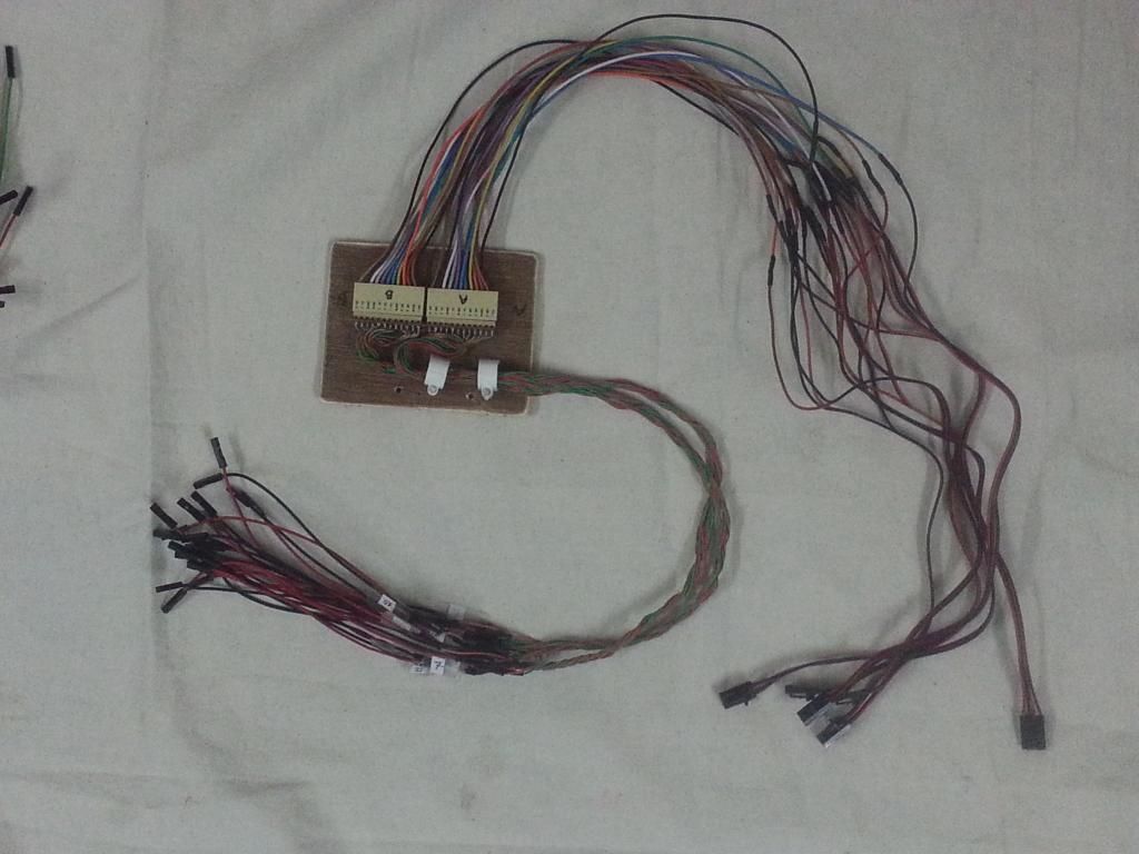 |
| The harness for 'Caution Panel' Will connect all 12 caution indicators on the panel. The two 12 pin connectors are the interface between Left Upper Console Panel and the main pit |
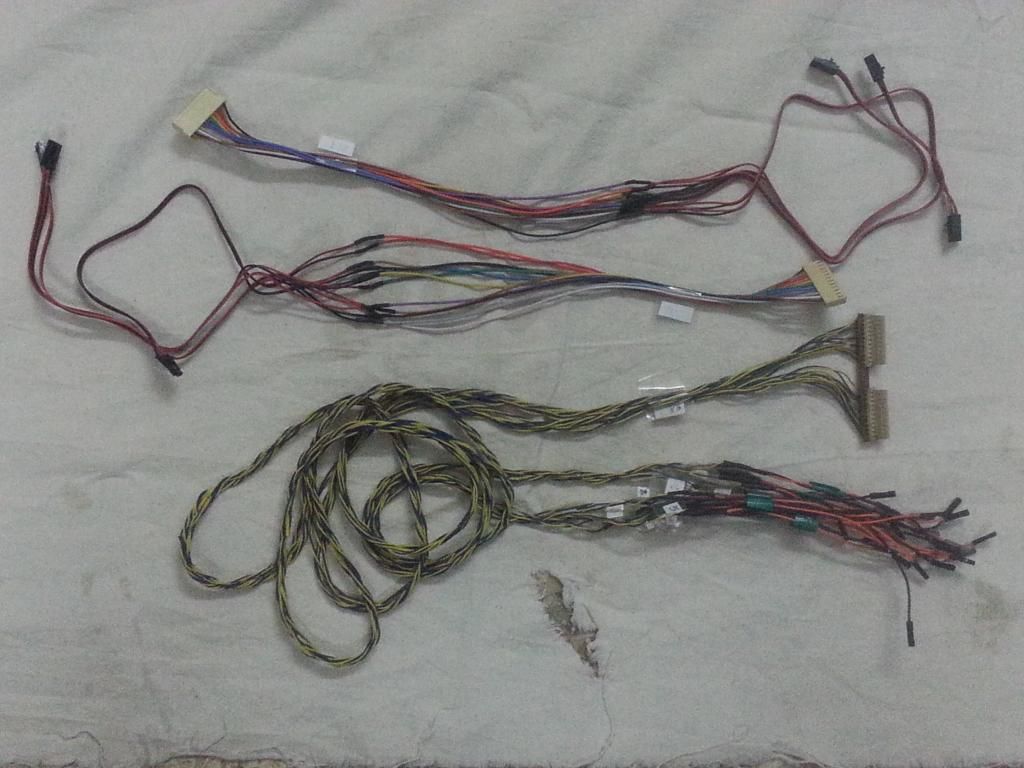 |
| Harness for the Left Annunciator Panel on the Front Instrument Panel |
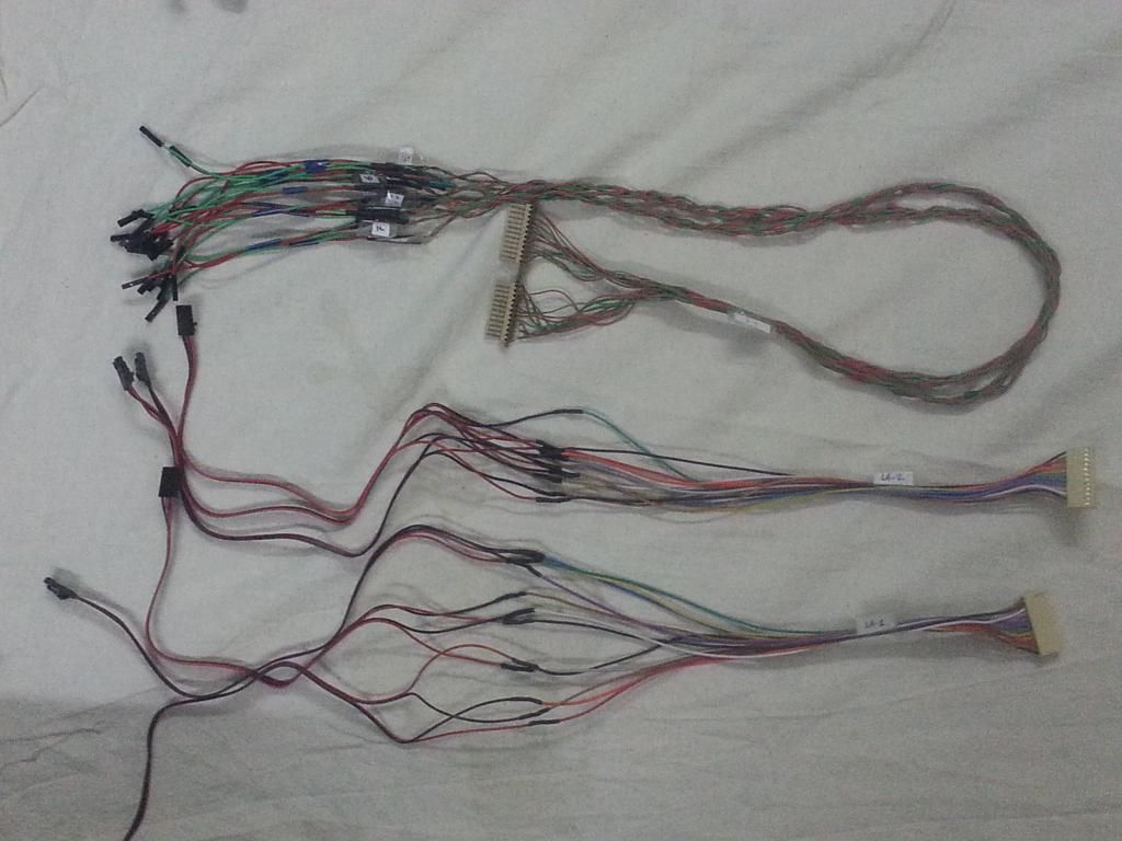 |
| Harness for the Right Annunciator Panel |
 |
| Harness for the 'Select Jettison Panel' including Flaps/Gear Indicators This harness doesn't incorporate the 12 pin connectors since it's a part of the main pit itself. While taking apart the pit, all I need to do is slide out the pin connectors, which are just push fit. |
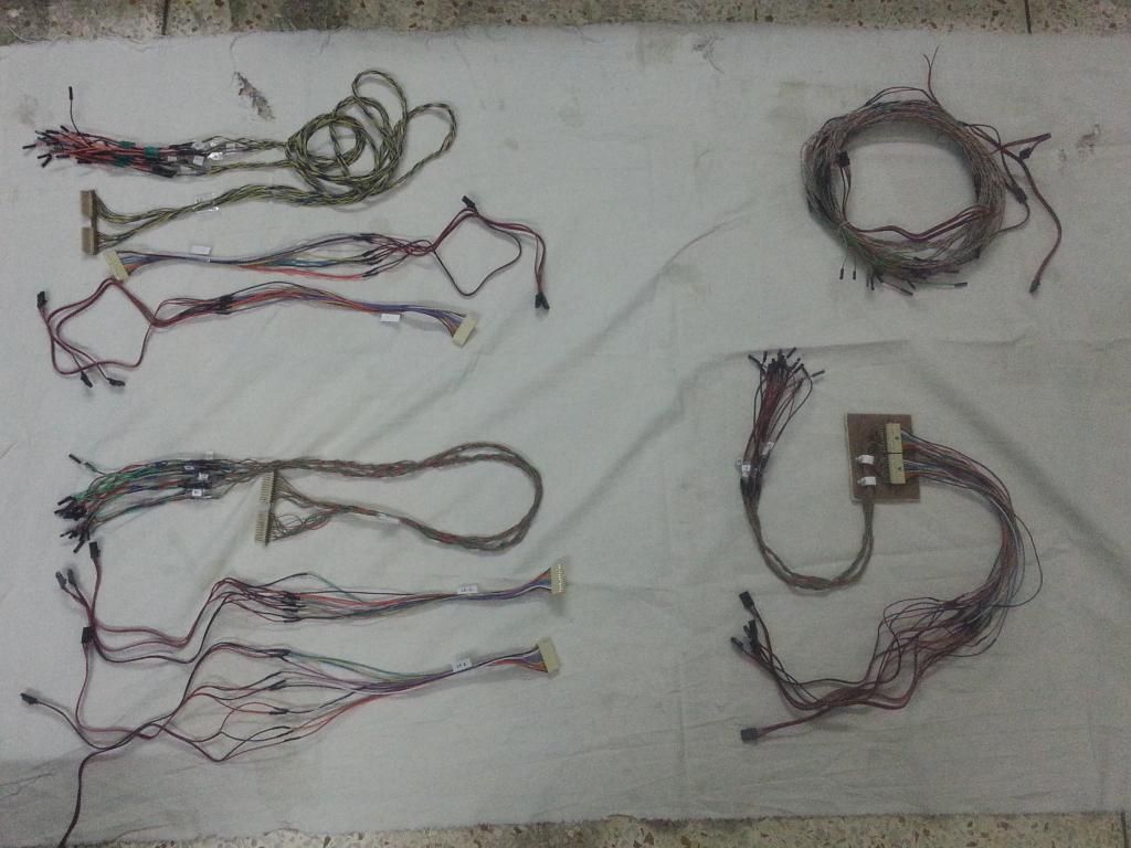 |
| All of them in one picture |
Will start mounting the cable harnesses during the week, and hope to finish it in the next weekend.
27 April 2014
Master Caution Panel
The plan for this weekend was to complete the "Master Caution Panel".
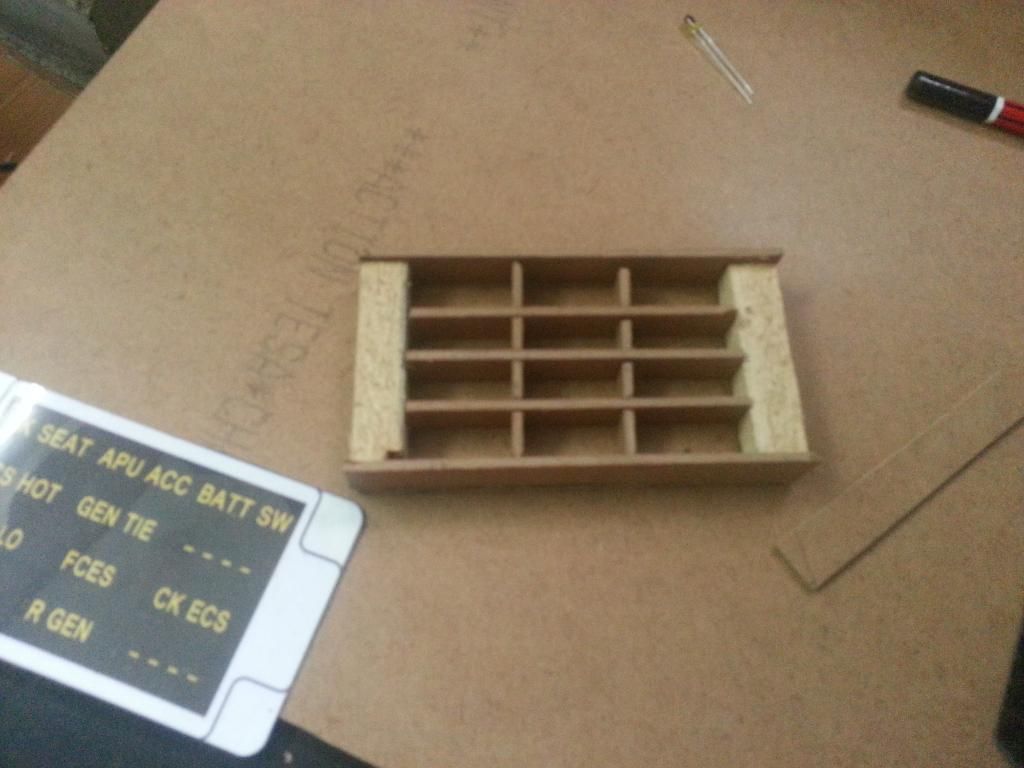
 |
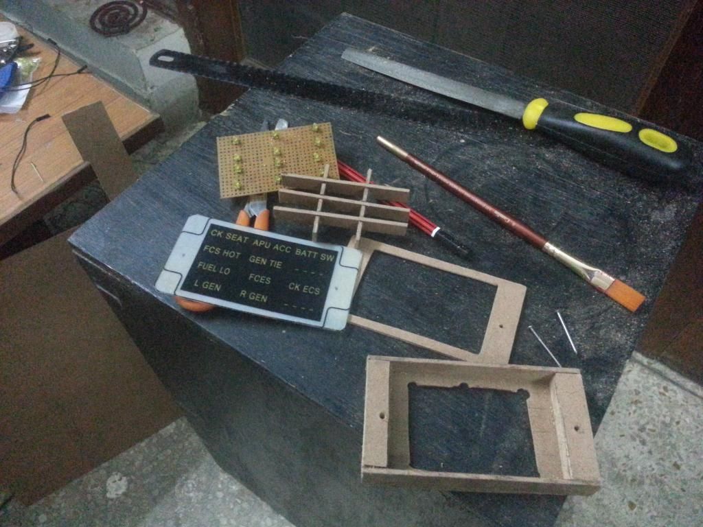
| The base material to fabricate the MCP is 2mm thick MDF Printed out a copy of the front facia and used it for measurements of width & height. Used the LED mounted on the PCB to assess the thickness of the panel |
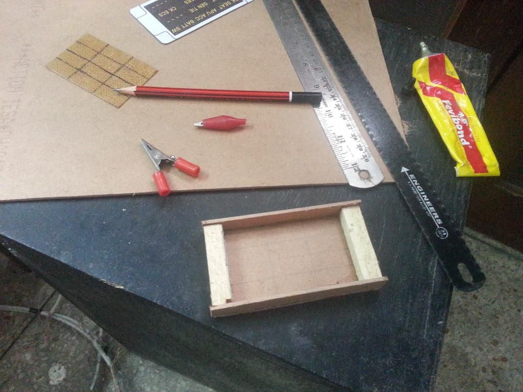 |
| The first cut |
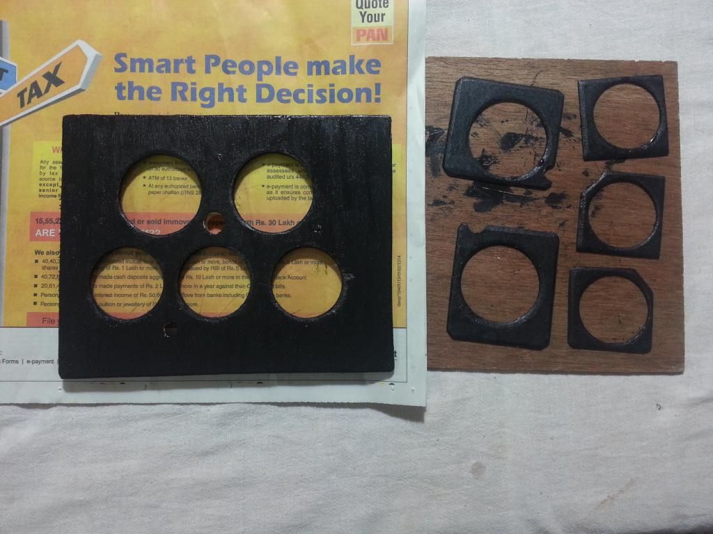
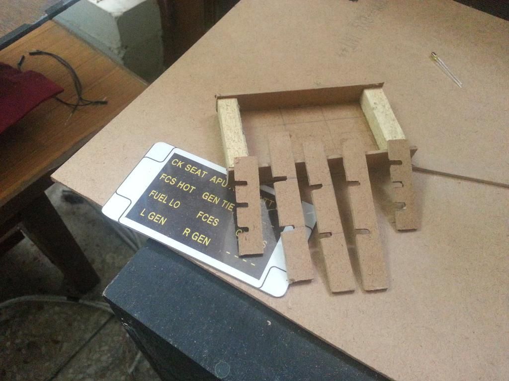 |
| The spacers are to 'box-in' the light from LED to the intended annunciator |
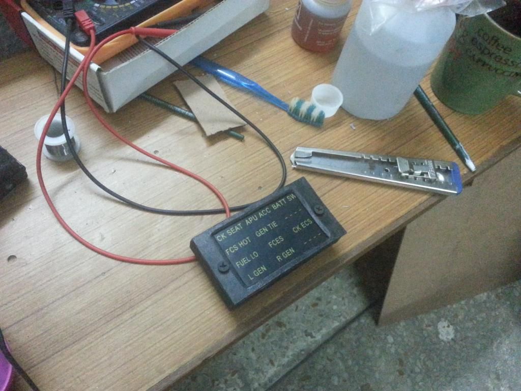
Making sure it all 'fits-in' correctly, before I finalize the build.
It does.
The base structure complete, front facia complete.
Soldered the LEDs to the PCB and correct spacing.
Ran into a glitch. Though the back face of the MCP had holes drilled in to accommodate the LED leads going out, but when I was testing the fit, I noticed the holes were not aligned correctly. So, had to make a cut-out, so that the PCB could fit easily. It wasn't planned this way, but, eventually turned out okay.
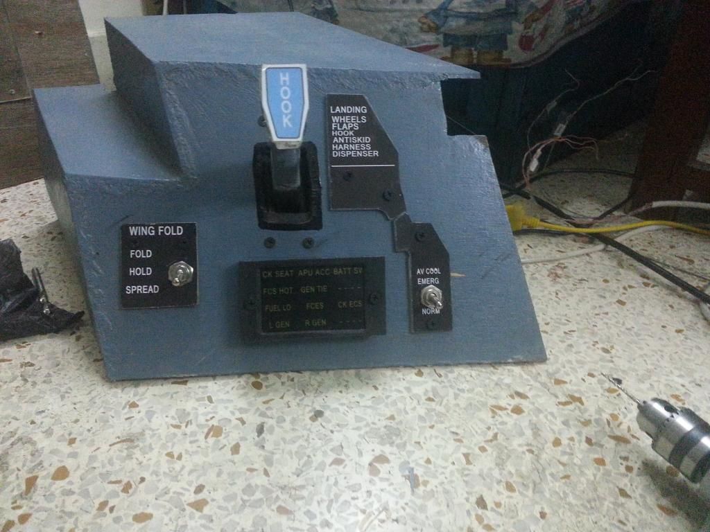
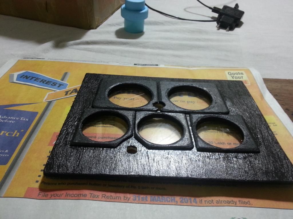
Painted all the parts with acrylic quick dry paint, and assembled the unit.
Tested out all the LEDs, again.
The annunciator front plate is laser printed on a transparency paper. During my initial tests, I had seen that too much light shown through a transparency paper and the overall effect was not very pleasing to look at. An additional layer of a cream translucent plastic sheet was added behind the transparency paper, and LED spacing (depth) was increased a shade, the effect comes out as intended.
Assembled the MCP on the Right Upper Console.
Still have another day left in the weekend. Will use it to make the harness (cable loom) for the MCP, and the remaining switches of Right Upper Console.
I thought, the Right Upper Console was completed today. Only noticed it now, that I still need to make a BUNO identification plate, a switch guard for the Wing Fold Switch, and a Hook Light.
Phew!!!!
This pit is never going to be complete.
20 April 2014
Random Pictures
 |
| Learning how to Solder |

Making my own 24 pin connectors

Making a PCB with 4 push button tactile switches

Making a 'harness' for 40 light annunciators on the Main Instrument Panel


Rear view of the Main Instrument Panel
All digital inputs of one BBI-32 board are completely used up by the MPCD. There are no analog inputs on the BBI-32. The BU-0836X board (shown unconnected in this picture) has since been connected to the remaining digital/analog inputs on the MIP.

Front View of partly finished Main Instrument Panel.
Since this picture, the EFD has been completed. The UFCP has already been completed, as a separate "Strap On" module. The UFCP has it's own dedicated micro-controller built in (a Teensey 2.0++), so it doesn't need any interface with the MIP except get mounted here.
The 'Selective Jettison Panel' visible in bottom left of the picture, is a custom design. I have used 2mm thick MDF for all fabrication. LEDs and tactile switches are built in. Due to my choice of materials, the panel is about twice as large as the actual panel. It's totally functional. But, this is going to the first part that I will fabricate in metal, when I learn CNC routers/lathe work.

Re-designed Left/Right Lower Instrument Panels.
I have used a different material this time around. The back panel is 5mm perspex, instead of 12.5mm perspex used earlier. The facia is now laser printed on special canvas. I had earlier printed it on a laminated photo paper, and wasn't very happy with the surface finish. This material also provides very pleasant back lighting capability.
Getting there!!!!
It's been a while since I updated the blog.
It's not because, there hasn't been any progress with the pit. There has been.
A lot of it.
But, because, I wasn't happy about posting the progress.
I spent about an year, planning this build. Spent another couple of years, working out the intricacies involved, fine tuning my build decisions, and then purchasing and collecting parts. The actual build has now been under progress for a little less than six months.
Till I started the build, I had absolutely no carpentry skills. I had never soldered a wire in my life. Had never flashed (programmed) a micro-controller. Had never designed an electrical/electronic circuit. All the preparation I did was a weekend of tuition's with a local carpentry shop, and then I went ahead and purchased my own tools, and commenced the build.
As the build progressed, I have noticed that my skills have generally improved, and finish quality of the 'pieces' is now much improved compared to my earlier attempts. At many places, I found that I could better design a part, compared to how I had fabricated it earlier (typically, the undercarriage lever mechanism, hook lever mechanism, the selective jettison rotary selector mechanism e.t.c).
I could have actually finished my pit, a few months back. But, that's when, I began to take it apart and rebuild all the parts that I thought, I could build better. Consequently, both the Left and Right Lower Instrument Panels have been completely redesigned, re-fabricated and wired with a new circuit. Ditto for the pieces mentioned earlier.
Also, I have been looking at work of some of the folks at 'Hornet Pits Forums' and have taken guidance in design of my pit. The designs some of these folks have put out are incredible. And all these are home pits, done by folks who do it as a hobby. Not by professionals. Awesome work guys.
The fact that most of my pit is made/fabricated out of wood means that at some places, some parts don't "feel" realistic. Ideally, I should have built them using CNC routers/metal work. But, those are skills that I presently don't have.
For the time being, I have decided to continue to finish the pit as originally planned, and call it Mk-1.
It's been too long that I have only been building, and in the past few months, haven't logged a single virtual flight hour. I need to get flying again. Soon.
Will take apart my pit again, and continue to rebuild it better and more realistic in subsequent marks/versions.
18 March 2014
Front Facia for Standby Instruments Panel
 |
| Getting there. The MPCD, Jettison Station Select Panel and S/By Instrument Panel Facia are in place along with Master Arm Panel and Spin Recovery Panel and also the L/R Annunciators Bank, Master Caution/APU Fire and Engine Fire Buttons. All LEDs and Buttons work as advertised. Am finishing up the EFD as I write this post. |
Next few weeks are planned to 'polish up' the Front Instrument Panel.
Oh, did I mention that I have decided to re-make the Left and Right Lower/Upper panels again. More on that later!
Multi Purpose Control Display (MPCD)
For the Left & Right DDIs (L/R-DDI), I had purchased the Thrustmaster MFD Panels. I could have purchased another set, and used one of them for the MPCD also.
But, just for the heck of it, I decided to make one myself.


Since this picture, I added twenty push buttons and two rotary encoders with built-in push switches. I could have added two more rotaries, but made a conscious choice not to do so. I also added a 5mm perspex sheet as the back plate.
To provide a realistic feel, each push button is also back lit with green LEDs.
The finished MPCD is now mounted on the Front Instrument Panel. Will post pictures in the coming blog posts.
But, just for the heck of it, I decided to make one myself.
Since this picture, I added twenty push buttons and two rotary encoders with built-in push switches. I could have added two more rotaries, but made a conscious choice not to do so. I also added a 5mm perspex sheet as the back plate.
To provide a realistic feel, each push button is also back lit with green LEDs.
The finished MPCD is now mounted on the Front Instrument Panel. Will post pictures in the coming blog posts.
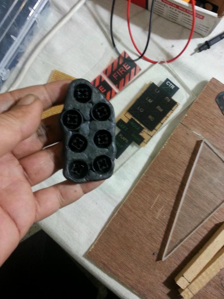
Jettison Station Select Panel
Here's an update on the making of Jettison Station Select Panel/Landing Gear & Flaps Indicator Panel.
Over the last few weeks, had to go through quite a few iterations to find a design solution that I could 'rig up' at home. Finally settled on the one that works. Just about, but still.
This panel was completed a few weeks back, but I wasn't able to break free to update the blog.
I do not have independent pictures of the final version of the panel, since I mounted it to the dash, before I could take any more pictures.
Over the last few weeks, had to go through quite a few iterations to find a design solution that I could 'rig up' at home. Finally settled on the one that works. Just about, but still.
This panel was completed a few weeks back, but I wasn't able to break free to update the blog.
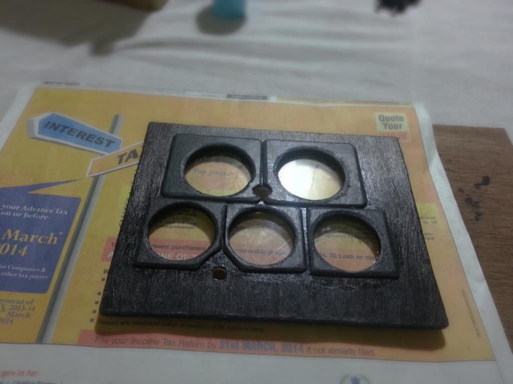
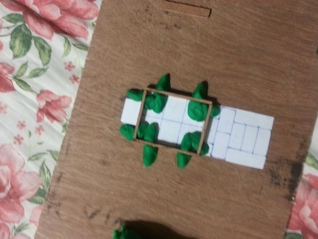 |
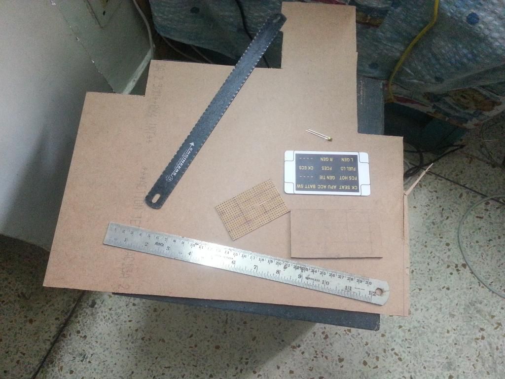
| Taking the measurements I have decided to work with 2mm MDF board for all my 'fine' detailing work. |
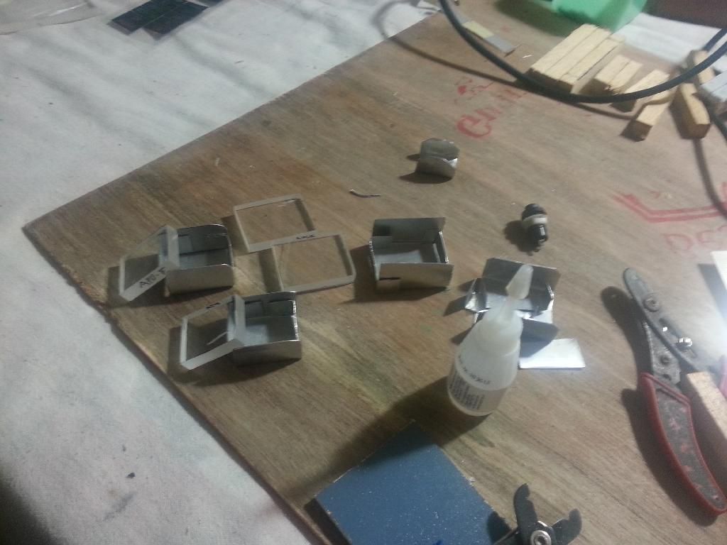
 |
| Making the Buttons Hacked a keyboard to pull out the buttons. They provide a nice tactile feel Stuck up the buttons using "M-Seal" plastic sealant |
 |
| Rear View of the button framework |
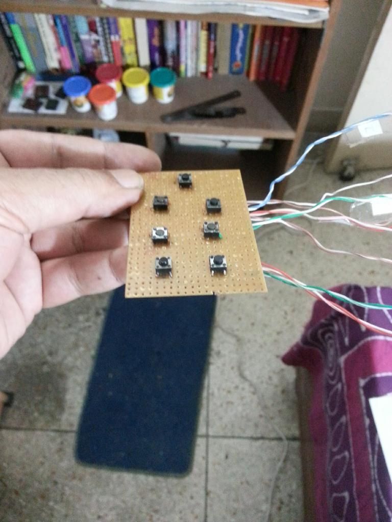 |
| The tactile micro-switches for each of the seven jettison stations |
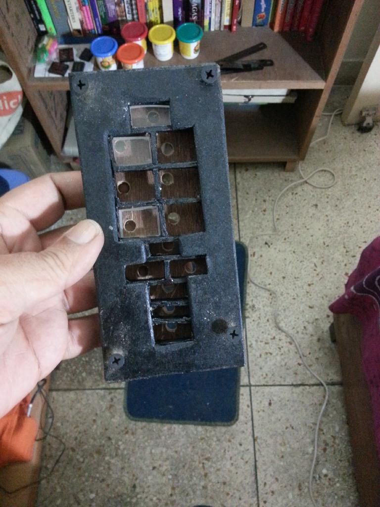 |
| The 'Outer Casing' of the panel The holes in the back plate accommodate the LEDs In the final version, they were hot-glued into place. |
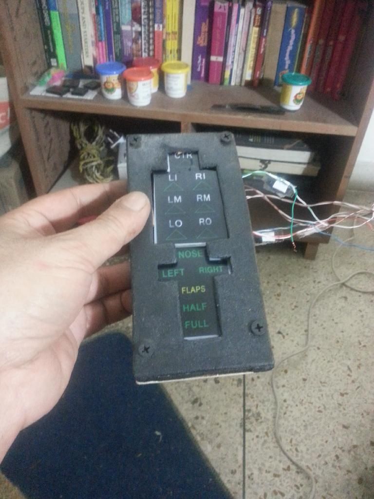 |
| Finished For the time being I broke it up and did it up all again Many times Wasn't happy with the feel of the button press in the initial iterations |
Subscribe to:
Posts (Atom)